Technology & Process Expertise
Proprietary low-shear screw design, advanced Moldflow analysis and precision mold manufacturing — plus prepreg layup, roll-wrapping and autoclave molding for finished carbon fiber products. The technical foundation behind Doolike's quality.
LFT Injection Screw Design Optimization
The core challenge in LFT injection molding is preserving fiber length during plasticization. High shear forces from conventional screws break the long fibers — reducing part performance dramatically.
Doolike Optimization Strategy
L/D ratio 18:1–20:1, deeper flights, lower shear rate — no barrier mixing elements
Speed maintained at 30–70 rpm — above 100 rpm causes shear heat and fiber breakage
Back pressure <5 MPa — avoids over-compression and friction at screw tip
Dual alloy steel (tungsten-cobalt coating) — high wear resistance, reduced fiber abrasion
Nitriding or chrome plating — reduces melt adhesion and fiber residence time
Before vs After — Performance Comparison
| Metric | Traditional Screw | Doolike Optimized |
|---|---|---|
| Fiber Retention Rate | 50–60% | 80–90%+ |
| Part Tensile Strength | 120 MPa | 180 MPa |
| Screw Service Life | 6–12 months | 18–24 months |
Design Objective: Reduce fiber shear fracture during plasticization, maintain fiber length >5mm, and ensure mechanical properties of the final part.
Precision Carbon Fiber Mold Design & Manufacturing
Mold Material Selection
| Category | Recommended Solution |
|---|---|
| Base Steel | Pre-hardened steel (S136, S136H) HRC 45–50 |
| High-Temp / Corrosion | 8407/8418/8503 non-stick steel; Cemented carbide |
| Coating Technology | DLC (diamond), CrN or TiAlN coatings |
| Surface Finish | Mirror-polished Ra <0.1μm |
Manufacturing Process Flow
Mold Optimization Results
| Metric | Traditional Mold | Doolike Optimized |
|---|---|---|
| Mold Shot Life | 200,000 shots | 500,000 shots |
| Surface Roughness | Ra 0.8 μm | Ra 0.1 μm |
| Fiber Retention Rate | 70% | 90% |
Auxiliary Process Technologies
Fiber Orientation Control (Moldflow Analysis)
Fiber distribution is predicted by Moldflow simulation, and the gate location and cooling system are optimized so that fibers are orderly arranged along the force direction — maximizing structural strength in the load-bearing direction.
- Gate position optimization for fiber alignment
- Cooling system design to minimize residual stress
- Weld line and warpage prediction
- Fiber orientation mapping for structural analysis
Post-Treatment Technology (Annealing)
Parts are annealed at 10–20°C below the resin melting point to release internal stress and reduce fiber-matrix interface delamination — significantly improving dimensional stability and long-term performance.
- Reduces residual stress from rapid cooling
- Prevents fiber-matrix interface delamination
- Improves dimensional stability over time
- Enhances fatigue life of LFT components
Carbon Fiber Product Manufacturing (Prepreg & Layup)
For tubes, sheets and custom parts we use continuous-fiber prepreg and select the molding process that best fits each part's geometry, fiber-volume and surface requirements.
Molding Processes
| Process | Best For |
|---|---|
| Roll Wrapping | Round & tapered tubes — best strength-to-weight |
| Compression Molding | High-volume net-shape parts & profiles |
| Vacuum Bagging | Panels, shells & large flat parts |
| Autoclave Curing | Highest fiber volume, aerospace-grade parts |
| CNC Finishing | Cutting, drilling, edge & surface finishing |
Weave & Tow Capability
- Weaves: UD, plain, 3K twill, cross & jacquard (incl. colored)
- Carbon tow: 1K / 3K / 6K / 12K / 24K / 48K
- Standard and high-modulus fiber options
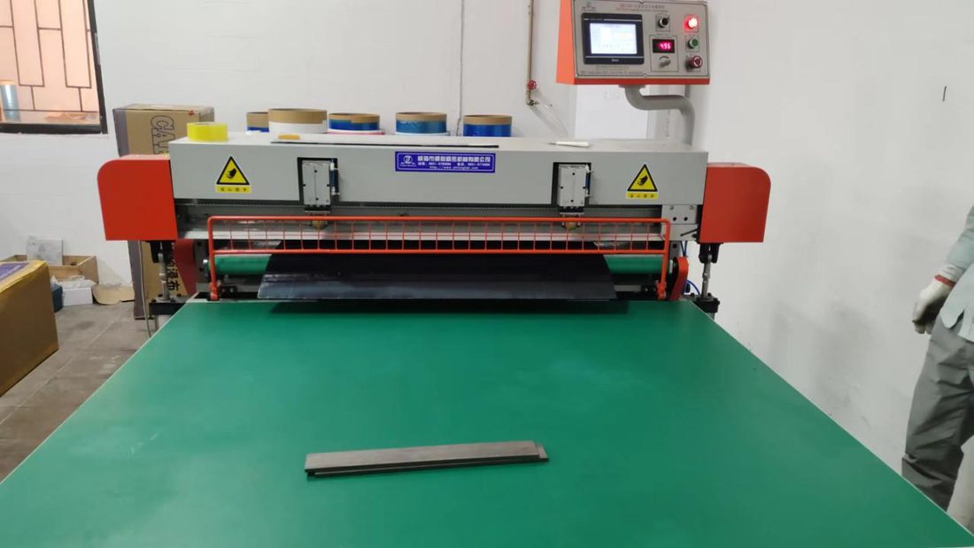
CNC machining of cured carbon fiber parts
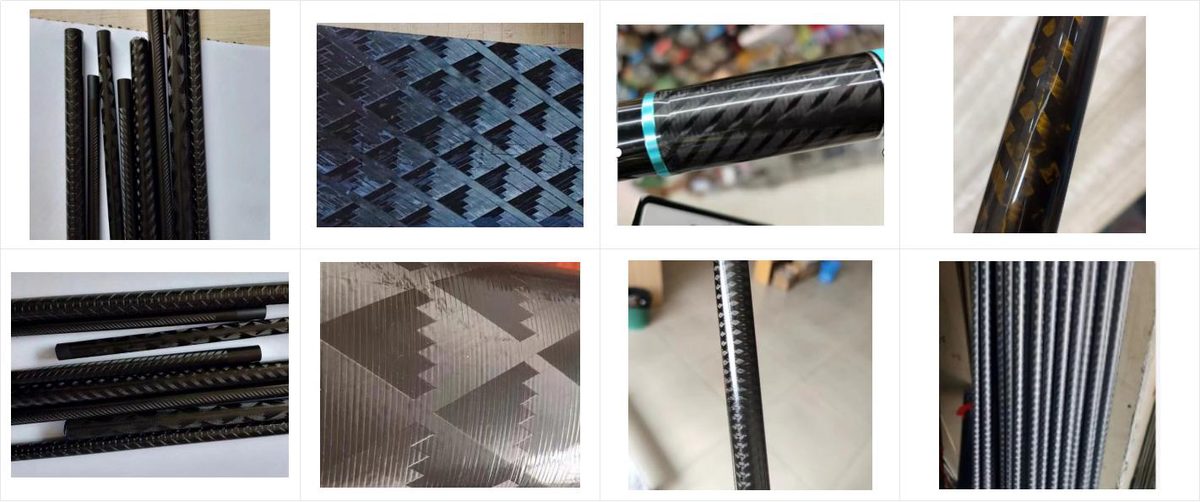
Selectable carbon fiber weave patterns
Discuss Your Technical Requirements
Our material and process engineers are available for technical consultations — from material selection to mold design and process optimization.
Carbon Fiber Technology — Frequently Asked Questions
We use proprietary low-shear screw designs (18:1 to 20:1 L/D, deeper flights, 30 to 70 rpm, back pressure under 5 MPa) plus Moldflow-optimized gating. This raises fiber retention from a typical 50 to 60 percent up to 80 to 90 percent, lifting part tensile strength from about 120 MPa to 180 MPa.
Optimized mold steel (S136 and 8407 class with DLC, CrN or TiAlN coatings and an Ra under 0.1 micron mirror finish) delivers up to 500,000 shots, versus about 200,000 for conventional tooling.
Roll-wrapping for round and tapered tubes, compression molding for high-volume profiles, vacuum bagging for panels and shells, autoclave curing for aerospace-grade high fiber volume, and CNC machining for cutting, drilling and finishing.
Yes. We run Moldflow simulation to optimize gate location, cooling and fiber orientation, and provide DFM feedback before tooling to prevent warpage, weld lines and fiber breakage.
Precision mold machining to plus or minus 0.01 mm and CNC finishing of cured carbon fiber parts to plus or minus 0.05 to 0.1 mm, with surface finish down to Ra 0.1 micron.
Yes. Share the load case and target properties and our engineers select the resin, fiber type and length, and process to meet strength, stiffness, fatigue and thermal targets, commonly to replace aluminum or steel.